I’ve just started using KiCad, and I’m really impressed. However, setting up a simulation can be awkward, because you need to match up the pin numbers from your schematic (which defines what is connected to what) with the node numbers that you ngspice model has.
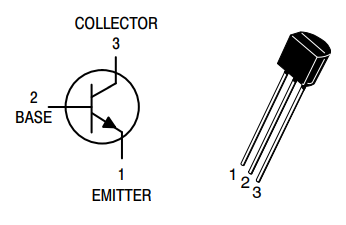
Most people encounter this first with transistors. eg. a typical BJT has the following pin assignments:
- Emitter
- Base
- Collector
However, our simulation models have nodes, and each node will correspond to a pin on the schematic and PCB, so we need to make sure that each pin is connected to the right node.
From the datasheet you’ll be able to get the pin assignments – e.g. pin 2 is the Base. Where do you find the ngspice node assignments? It depends on the type of spice model you’re using.
- Built-in .MODEL. These are used for standard components, so the behaviour of the component can be defined with just a few parameters – e.g. for a basic simulation all you need to know about a resistor is the resistance. There are 17 types of model.
- Custom .SUBCKT (Sub-circuit). These can be used for components that don’t fit into the standard categories, or for a complete add-on board.
Which one is it? In KiCad, look at the spice model editor:
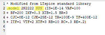
.MODEL
To get the information you need, you’ll need to look at the ngspice manual.
This includes the list of 17 standard models (reproduced here):
| Code | Model Type |
| R | Semiconductor resistor model |
| C | Semiconductor capacitor model |
| L | Inductor model |
| SW | Voltage controlled switch |
| CSW | Current controlled switch |
| URC | Uniform distributed RC model |
| LTRA | Lossy transmission line model |
| D | Diode model |
| NPN | NPN BJT model |
| PNP | PNP BJT model |
| NJF | N-channel JFET model |
| PJF | P-channel JFET model |
| NMOS | N-channel MOSFET model |
| PMOS | P-channel MOSFET model |
| NMF | N-channel MESFET model |
| PMF | P-channel MESFET model |
| VDMOS | Power MOS model |
Go back to KiCad Spice Model Editor
So, now look at the section of the ngspice manual for BJTs:
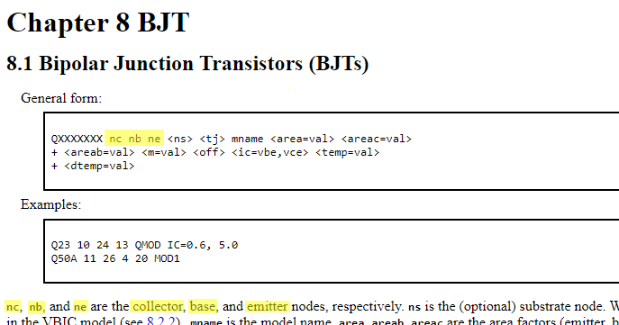
This tells us that ngspice expects the nodes to be listed in the order collector, base, emitter.
We’ll use this later.
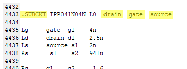
.SUBCKT
Sub-circuits can be easy to figure out, or they can be hard, depending on whether the creator of the model has made sensible choices about the node names.
Look at the KiCad Spice Model Editor – this example is from a manufacturer spice model of an N-channel MOSFET, that has chosen to use .SUBCKT instead of .MODEL:
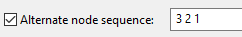
Alternate Node Sequence
Now we’re ready to fill in the Alternate Node Sequence box in KiCad:
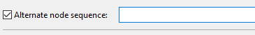
In this you write a list of the pin numbers, separated by spaces, in the correct node sequence.
e.g. for our BJT example we know that the correct node sequence is
collector, base, emmitter
Recall our pin assigments:
- Emitter
- Base
- Collector
So I’ll rewrite the node sequence with the pin number in brackets:
collector (3), base(2), emmitter(1)
Now all we need are the pin numbers, so strip out everything else:
3 2 1
And put that in the Alternate Node Sequence box: